Bessler 401
Measurements
Twins
Prima/Secunda
MT
Summary
Maschinen Tractate
If there was ever a book that would turn me into an old man this is it. I have spent thousands of hours combing through this book and its descriptions.
Like most of Bessler's stuff this book talks mostly about the two-way wheel with some snippets of the one-way wheel.
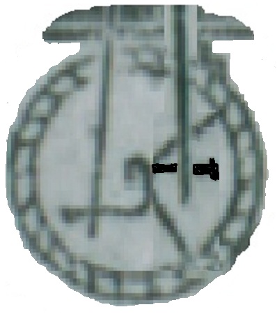
After looking at the drawings for a while patterns began to emerge. All most too many patterns. There is the tens series where each decade drawing (10,20,30...) seems to have been laid out ahead of time. When you get into the teen numbered drawings they seem to be repeated when you add ten or twenty and so on. Then pairs and groups of drawings started making more sense as being connected together or a differential comparisions of the two wheels that reverse and flip-flop who's first. Other groups of two or three drawings seem to be focused on one particular wheel. The wobbly weight ladder group, the signature pendulum weight group, etc., etc. There is another small set of drawings that have Bessler's other signature mark the combined NB as mentioned in the Measuring page. The beginning of the leading paragraph in this book and drawings eighty-one, and ninety-six. There is also what looks like hand written marks that could be additional NB's in drawings seventy-three, seventy-four, and one hundred and three. In the final category of drawings he seemed to just be having fun with unrealistic or fanciful Rube Goldberg devices.
The following is my attempt to interpret what Bessler was trying to say for each drawing.
On the first page of the actual book Bessler declares the solution to his wheels are within these pages. No figure by itself contains the motion but by combining certain figures, a movement can be found.
through 8. hold little importance because they are mostly just describing what won't work. There are a few things scattered here and there that could be called initial hints.
Here Bessler points out that ball weights are of no use in seeking perpetual motion. He then goes on to say what will work is weighted arms that are interconnected. I also find it fascinating that Bessler kicks off actually talking about something important till this specific number. It may have to do with Hebrew form of numerology or it could be his way of trying to make things a bit more confusing.
The first of the decades. Arms should be long and curved presumably to position the weight where it could otherwise not go. Later he will depict this figure differently and show the “correct handle construction”.
The double rows of weights are important but in a different configuration to be revealed in an unspecified place.
The guide at the lower left demonstrates the effect to be sought on the wheel. This could be a reference to twins number 24 latch and lock. Causes the wheel to shake a great deal comment is interesting as it may indicate that a greater portion of the push power comes from the lower weight than the top one.
This is one of about twenty wheels that rotate counter clockwise and with thirteen being a dubious number Bessler may have made it backwards for a reversal of bad luck. When the weight above is to be lifted it should be snapped up quite quickly.
This drawing introduces the first of several drawings that show two weights on opposite sides of the wheel being lifting straight up at the same time. Bessler finally tells us where to look for his best clues about the wheel, in the end of the book.
This drawing shows the effective overbalance of the running two-way wheel with the outer most ring of weights. These weights slide in and out with no lateral movement and are like the stampers from the twins and Prima in some respects. The weight at the very top 12 o'clock position is rectangular like a hammer head to make it stand out. The prime mover mentioned is assumed to be the weight(s) that must fall in order to raise the weights as shown.
Bessler shows how the weights are connected together with the two letter A's. You will see this relationship a numerous times in the following pages.
There are springs in Bessler's wheel. On this drawing most people look at the springs that are stretched out around the top and right of the axle thinking the springs are pulling up the arm that follows. The less obvious but more important thing to look at is the bottom where the two springs are compressed. The next arm to the left is slightly lifted. The spring appears to be compressed very hard for a short period of the rotation and its pushing travel is limited to a few degrees of lift before the line becomes broken.
Bessler says this IS the previous drawing but still not quite right. The principle being demonstrated is that the arms sagging down and backward for a time of the rotation does not help but it does not hurt either, which is counter to personal experience. Then he gives a cryptic hint that the drawing tells more than it shows but he will show more than tell later.
The subject of sagging arms continues.
The second decade and in the text he suggests moving the smaller weighted arm to get the horse before the cart. The long arm being the horse and the short arm being the cart. The A's in number sixteen would fulfill the concept quite well.
Bessler states the obvious that the arm at the lower left C in the drawing would not fall in so soon....... but what if it had a compressed spring like number seventeen and a triggered latch from the twins or Secunda to release it at the right time and pop it up? They both appear to be at the same approximate part of the rotation. I really don't have a lot of faith in this configuration but I promised to expose all my thoughts.
This is a very tough read but it does not seem to be anything terribly important that isn't made up for later.
He kind of blows this one off too, but twenty-one through twenty-three do seem to be grouped together.
This drawing and the one that follows are very mega important diagrams. Hinged metal rods not rope are between the solid wall and the moving weighted arm and since the rods are solid they could also be used to push. He says there is more to tell about the drawing.
The longer rods appear to be an improvement but they must not be allowed to make a straight line as shown on the right side of the drawing. Even though it must be changed a lot but again he punctuates this drawings importance with the strong and somewhat defiant expression, “Mark my words.”
Bessler introduces the sliding weights in a new configuration but now they are sliding sideways not vertically. Drawings numbered twenty-four through twenty-seven are possibly more about the one-way wheel. The line from the left weighted hinge B to the rim hinge point of D is hyper extended toward center and B would have to be a tremendously greater weight to even make it a straight line.
Very similar to the previous drawing except maybe a little more practical. Bessler flaunts the thought of multiple units on an axle but I think its more jokingly.
The drawing and some of the text appears to be a bit of a red herring allowing Bessler to quietly say at the end of the paragraph that the resulting torque on the wheel is much greater than the force required to lift the weights.
Bessler appears to be saying that the two-way wheel above delivers four times the torque to the rim of the wheel than is required to lift the weights and on this one-way wheel only two times the force required to lift the weight is delivered as torque on the wheel.
Here we are at the third decade and quite a long description. It is an introduction of how the pivot point for the small weighted arm is oriented in respect to the main axle. The drawing also has a handle operated by a hand, a likely follow up from number ten.
This is a combination of some of the previous concepts and there is more to the wheel but this drawing only shows the problem. The problem most likely is the efficient lifting of the upper and lower weights.
He keeps developing the idea of long weighted arms lifting short weighted arms.
Again.
And again
Even if the long arms in the above drawings are “lifting” the short arms this drawing demonstrates that there may also be a squeeze that is applied that may assist in lifting the weights.
This drawing is an either or both thing. The latches at the top and bottom could easily relate back to the locks in the twins. The implied result being that the lifting arms will so much overwhelm the short arms that the action must be delayed until the right time in the rotation. The other thing is the inset drawing to the upper left. The short arm appears to have a rectangular mounting bracket at its base that surrounds a square board. If the weighted arm ever achieves a hanging orientation the weight would be even harder to lift if done by turning the square board. It must be important however because Bessler went to the trouble of carving it out and inviting the reader to gather as much information as possible.
A perfectionist doesn't just happen to misplace a drawing within a book as he states. This drawing demonstrates that there is likely a spring interconnecting the top and bottom weights together. The thing that is odd is that only two of the six springs are stretched. The ones at the nine o'clock and ten-thirty positions yet the arm at the seven o'clock position is being pulled farther than gravity would dictate. Bessler says the correct springs or location are hard to find. One final note this drawing does fit in with numbers fourteen through sixteen and if you add twenty to the fourteen through sixteen it would be followed by thirty-seven through thirty-nine so this may be a continuation of the former numbers.
Bessler introduces the lazy tong device and it too is in between the top and bottom weights. He says there is more to this invention than the previous one but the correct application is not shown yet.
Another tong device and I wonder if it is more related to the squeeze or the lift because one weight falls as another is lifted. This drawing is interesting because the left side weight sliding horizontally would much easier than vertically lifting one, however it would have to be lifted uphill at some point to return to the rim at the top.
The fourth decade and a significant number in the Hebrew number system. Oh, look, another handle. The sliding weights on the horizontal board in this figure are a mystery but could be related to parts found in drawing thirty-eight. Bessler doesn't mention them but again there has to be something to it and it may be related to the previously introduced squeeze.
Right away we have a squeeze model again and the sliders are vertical. He states that the tongs are very important and how they operate better in the horizontal aspect than the vertical. There is a discrepancy between translations so at this point the tongs either ARE or ARE NOT the exact correct artistic application.
Again the squeeze seems to be an important element. The inset drawing is unique to say the least. Though it is difficult to see the multiple ring weights at the top and bottom are connected as pairs by rods. The center most connecting rod goes to the closest pair of weights. As you go outward to the next pairs of rods you also go up to the next weight not unlike the steps of the twins stampers going up each step.
I have studied this one carefully just in case, but there is nothing here except it is an effective transition to what follows.
Bessler is slyly showing us something about the two different types of wheels in this and the following drawing and he does it again a little later. This is the two-way wheel and the only thing I see is the high gear ratio of the driving wheel against the driven one. It is interesting that the angles of the increased weight at the top and loss at the bottom closely coincide with the depiction in number fifteen.
This is the one way wheel and again the angles of effective weight increase and loss are shown on the big wheel. Now you know why the two-way wheel has twice the torque per pound.
I don't know what to make of this drawing. A feeling says it holds something valuable but I don't see it. It has the ladder element with the balls wobbling left and right that is very similar to number six, the next drawing and elsewhere.
Bessler takes you all around the page and drops you off at the letter K and says “the rest of this machine” is very important. The rest that is left is the spring that appears to aid the tongs for the beginning of their travel upward like what we saw in number seventeen. The ladder element is here on the face of the wheel. Speaking of springs seventeen, plus twenty is thirty-seven, then to forty-seven... is that a pattern? Twenty-seven appears to have been skipped in the pattern. This is also the only drawing with its number anyplace other than in a separate box that is external to the machine.
This is the one-way wheel with a square axle and idler pulley like number thirty-six.
This is the two-way wheel with square axles at top and bottom.
Another drawing with square axles with something new is introduced. The center section C flips out to hold the arms out while the square axle is in the diamond shape. I don't know why or how this really works but it seems to be a big deal too. Could be related to the locks and latches from the twins and Secunda.
Bessler introduces a ratchet type mechanism that also appears to be very important.
Bessler explains that the wheel is not driven by heavy blows from a hammer weight. He may have made his wheel to be loud to draw attention of crowds. It is important to note that the loud banging was only associated with the two-way wheel. The one way wheel was reported to make scratching noises like stick rubbing.
For all of the interconnecting arms that wrap up and over the top of the figure, Bessler says it is lever G that lifts the weight.
This is the last page with any meaningful text except for the 'Toys Page' and a couple of notes close to the end of the book. The squeeze concept is uniquely devised. Should be the two-way wheel with the tongs lifting the weight. Note the tongs are horizontal like forty-one. Is this the exact correct application?
This top figure suggests the weight is lifted with a device that is not permanently attached to the weighted arm and/or showing a specific gear ratio between lifting forces and the load. The figure at the bottom may be associated with how the spring gives the weight a flip start in its path being raised.
The main thing I see here is the squeeze is now coming from the wheel like in drawing fifty-four. This is also the first drawing that depict anything other than solid physical weights.
Through 59 are fill.
This is the sixth decade. This drawing attracts attention because of the sudden uniqueness and precision of this and sixty-one. This figure suggests the idea of a constant tension between all of the arms either with ropes and or springs or both.
See above and the items labeled D are similar to the sliders in drawing number forty.
through 86.Mostly fill. Bessler repeats themes of sliding weights and long arms lifting weights more or less in the number sixteen configuration of the A's, square axles. Seventy through seventy-two are interesting. Eighty stands alone from anything on either side of eighty-one has the NB.
87. through 89. All have handles. Eighty-eight is the only one with a balanced load and is the only one whose handle is moved back and forth instead of up and down.
90.The ninth decade. This drawing also has uniquely better craftsmanship compared to drawings on either side. Gearing ratios, long arm, short arm size ratio. And just how does the water get from the pumps on the ends get to the wheel to flow out the bottom?
91.Even though totally impossible this drawing is interesting. The suspension bracket from the ceiling so it could slide up and down the sharp hook shape that was seen in numbers fifty-six at the end of the bellows, sixty-one between the wheels, ninety-two, one hundred eighteen, one hundred twenty-two, and one hundred thirty-seven.
92.through 95 hold little interest at this point.
96.Has the NB and the signature weighted arm. The two wheels at the left are the top and bottom weights yielding output energy.
97.This drawing again shows what part of the rotation the one-way wheel lifts its weight and where it drops out of the effective range again.
98.Signature pendulums and the energy flow path through the one-way wheel.
99.The flow of energy in the two-way wheel.
100.This is the most artistic rendition from here to the end of the book and the tenth century mark. I also get the feeling that from here to the end of the book is what Bessler referred to as showing more than telling in the end. This drawing is the two way wheel and is showing that the short arm turns perpendicular to the main axle.
101.The one-way wheel small wheel same axis of the axle
102.One-way wheel because of where the water enters and exits the wheels. The interesting thing is that the spokes of the wheels rotate clockwise one hundred and thirty-five degrees as you go from top right to bottom left. The wheel actually bobs backward in the fifth wheel. The arms that interconnect the seven wheels are separate short arms so they do not interfere with positioning of the spokes. Also note the lever arms at the top to the two single pumps. Their difference is size suggests that the one pump has more positive influence than the other side.
103.This is the two-way wheel because of the water in and out. There are three sets of four wheels with each side rotating in the opposite direction. The first two wheels are the most important with the left one moving upward and attached with a rather conspicuous looking hook. The slightly lower right wheel is attached with a totally different type of arm and it is moving downward. This second wheel is half way to the bottom of its travel yet the shaft to the pump above it is still fully in contact with the ceiling. The double pumps at either side are another clue that tie this drawing to the two way wheel.
To get a clearer picture of this drawing take part of the right hand wheel and mirror it horizontally and place it on the left wheel as above. Another thing is the hand drawn sketch to the right with square axles. It looks to be in Bessler's own hand. This hand sketch would most likely have been a permanent addition to the final edition of this book.
104.This is the last officially numbered page most everything else is hand numbered. The rest of the pages have a black rectangle to carve out the page numbers for the final printing. There appears to also be a couple of drawings Bessler wanted to also include that he sketched in on the backs of other pages that are not even in the hand numbered sequence. This drawing might be trying to show additional detail of the linkage of the two way wheel that could not be shown in number one hundred three.
105.There have been a few roller arms like number fifty-six and always wondered if they were related to the squeeze.
106.This is the first of three quietly important drawings. This is the one-way wheel and C is the angle where the weight is lifted whether the wheel is creeping forward or running full tilt. Notice that the water line or balance line is a little above the axle.
107. This is the stationary two-way wheel with a balance level just below the axle
108.This is the running two-way wheel. Its center of gravity is nearly at the top.
109.Fill.
110.Square axles and a narrow board block in the middle and possibly a slider from forty in the center.
111.Hidden axles but apparently time passes with a wide block in the middle. The weights in the cones on the right side appear to be broken into two pieces. The weights on the left side look like cone shaped buckets being carried up.
112.Cones inside the chain can open, as well as, the outside ones in the previous two drawings because the block in the middle is gone. This happens when the square axles are diamond shaped and it contradicts what was seen in drawing fifty. At the bottom of this figure there is also a curious ball weight on the end of the cone at D.
113.Upside down is another reversal of dubious thirteen. I believe the drawing is right side up and just the letters are inverted. Since the rising short arms on the real wheel fold up sideways he is just showing that the arms do NOT hang down or fold backward to the rotation of the wheel.
114.See number one hundred eight.
115.See one hundred seven.
116.Hyperbole.
117.Believe it or not I found this drawing fascinating after bypassing it hundreds of times. The device to the right has three tubes running up and one down. If this is the two-way wheel this may be involved with the cryptic center of the measuring stick in the DT twin. Even if three stampers are raised as steps. One of them still has to be at the bottom.
The left side of the drawing is one tube or stamper up and one tube down. The two G balls are maybe acting as one and the H balls are acting independently. This looks to be representing the one way-wheel.
118.The eight weights of the two-way wheel are represented by the eight sharply angled tubes as described in number ninety-one. The tubes are balanced on each side and the top two tubes combine into one. They all work together to contribute to the flow of downward or forward motion of the big arrow.
119.The two way wheel has two springs per weight/arm/stamper.
120.The one way wheel has one spring per whatever.
121.The two way wheel just because it is more complicated.
122.The one-way wheel for its simplicity. The pumper arms at the top and the part that hangs down to E looks a lot like a balance scale common to the period.
123.The one-way wheel because similarity to the weight in Secunda. This shows that when the weight moves it swings nearly one hundred eighty degrees.
124.This shows the paths of the two individual weights on the two-way wheel. The ladder figure and the ratchet figures are attached.
125. and 127 all seem to be one particular wheel.
128. and 129.seem to be the other wheel. Notice the blocks at the upper left and lower right of the figure to the far right.
130.to 132. are anybody's guess.
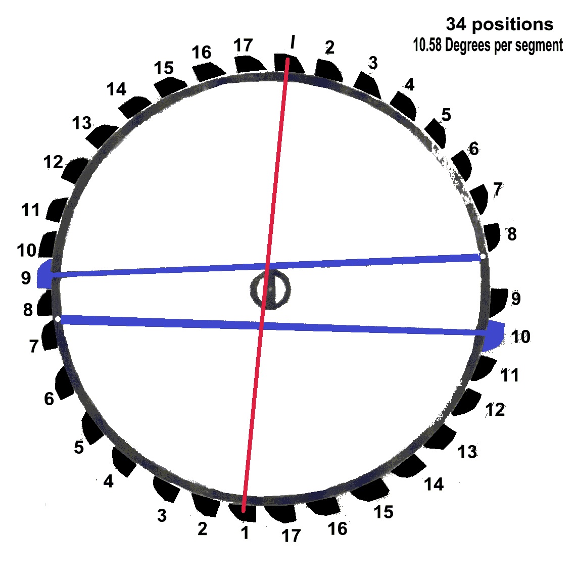
133. One of the more fascinating drawings. This is the one way wheel. The bottom inset shows that the long arms extend from one rim to the other where the weighted short arms will be connected to the ends. The weights around the full circle wheel is a conundrum in itself. If the weights are cross connected the weighted arms as shown don't line up as being truly across from each other as it appears in the drawing. Below is the wheel numbered as they would have to be as shown in red. It is rather odd that Bessler chose thirty-four instead of thirty-six intervals so I will suggest the possibility that the weights may occupy a particular position twice. That could fix the discrepancy of the opposing arms being connected two different numbered weights and it would fit with drawing one hundred two quite nicely.
134. This is the two-way wheel. The bottom inset shows that the long arms are mounted on the center wooden axle shaft with an extra corner hinged framework. Very ratchet like teeth adorn the weights on the outer rim. The full wheel on the drawing depicts that the arms at the three and nine o'clock positions lift the weights at the six and twelve o'clock positions.
134A.This is the first of two hand made sketches that Bessler would have likely made permanent drawings in the final version to this book. A curious thing worth studying it seems to have originated from the lamp black that rubbed off of the facing page of drawing one hundred thirty-five. It features a long arm from rim to rim with pendulum weights that are rotating while suspended on sticks extending from the bottom of the long arm. Not sure what it really means but the long arms line up with arms on the next drawing.
135. Back to the theme of the sliding weights and here the stampers slide through the wooden shaft.
135A.The second hand made sketch. The text at the top gives a hint of this drawings importance. The characteristics demonstrated here are quite fascinating when you analyze it. The three pairs of weights that are geared together have the unique property of requiring very little effort to change the weights positions. As one weight is lifted the other equally falls giving them a balance of forces. Even if the individual weights were several tons each the force required to move them would be entirely attributed to the friction in the bearings at the pivot points.
The corner hinged rectangle frame that is mounted through the center vertical post is in many ways similar to drawing one hundred thirty-four and is another unique physics demonstration. The two sides of the rectangle can also be raised and lowered regardless of the position of the two sets of geared arms in spite of the apparent overbalance on the right. The effective total weight is actually equally distributed. On the other hand, if the foot stand at the bottom is not wide enough the whole stand would fall over to the right with the weights in their current positions.
136.This figure has the signature pendulum weights. Most people see that the weights to the top and right are further from the center but the center posts are also moved and appear to be driven by springs near the axle of the wheel.
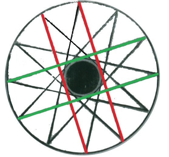
137. This drawing has been used by many people to support theories but I disagree with most of their conclusions. Primarily what I see are sets of perpendicular lines as seen in the drawing below.
138. through 141.The famed “Toy Page” and again all about the two-way wheel. The figures on the right are the set up for the rest of the page. Both figures A and B have equally spaced sets of balls up and down their sticks. In figure A all of the balls are on the left side because of the opening and closing of the mechanism. B is simply a timing record with the balls on one side representing the top of the wheel and the other side the bottom. Figures C and D are attached to figure B at certain places in the timing marks. C is attached at the top or bottom and D is attached midway between the top and bottom. C and D would necessarily be perpendicular to each other. Both C and D are also attached to the lazy tongs on the left and this provides information about the leverage or directional movement as attachment points.
The angles at the top of B are likely of great importance.
The hand sketched figure at the bottom is a toy top. I have seen and played with similar ones as a kid. Bessler added the toy top to demonstrate that a heavy weight can be lifted of its own accord. In this particular circumstance it is the centrifugal forces and the shapes at each end that push the weight upward rather than a mechanical arrangement of separate weights on the wheel.
Click hereto go to: Summary.
You can send email or suggestions to: me @ mikeyned.com.
Copyright ©: All rights reserved